It calculates the reactive power to install to obtain the desired power factor (cosø) starting by the initial power factor (cosø).
Initial power factor (cosø):
cosø
Required power factor (cosø):
cosø
Active power
kW
Circuit voltage
V
Working frequency
50 Hz
60 Hz
| Results | |||
| PFC reactive power to install | kVAr | ||
| Initial apparent power | kVA | ||
| Final apparent power | kVA | ||
| Percentage of saving | % | ||
| Capacity of each capacitor to install | µF | ||
| RMS voltage at capacitors | V eff | ||
Notes.
To obtain optimal results the PFC must be local (close to the machinery),
in this way you will recover also the loss on the supply line.
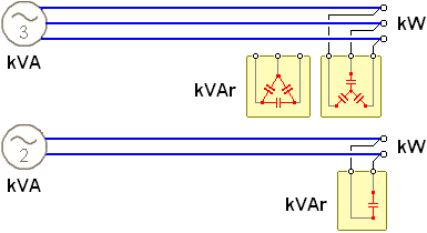
Example of characterisic cosø to correct :
Example of correction a 32 W neon lamp :