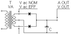
Dimensioning of DC power supply with stabilized output and linear
voltage regulation, full wave rectifier with silicon Graetz bridge
and leveling capacitive filter.
The stabilizer can be any of the linear IC stabilizer (not switching)
with fixed or regulable output voltage or also a circuit made by
discrete components.
Nominal voltage of the PRIMARY winding
V ac NOM
Nominal voltage of the SECONDARY winding
V ac NOM
Transformer nominal power
VA NOM
50 Hz (sinusoidal)
60 Hz (sinusoidal)
Total capacity of the filter . . . C
µF
Define automatically an appropriate capacity
based on the above data
Minimal admitted voltage difference between input and output of the regulator.
(e.g. 78XX, LM 317 = 0.6 - 1.7 V)
Vreg
Real supply voltage:
%
V ac EFF
Real applied load:
%
VA EFF
A EFF
Required stabilized output voltage:
V OUT
| Results | |||
| Transformer : | |||
| Theoretical transformation ratio | |||
| Percentage of characteristic voltage drop at the nominal transformer power | % | ||
| Secondary no-load voltage with real applied supply voltage | V max | ||
| Voltage drop on the secondary winding related to the applied load | V ac | ||
| Real output voltage of the secondary relative to the applied load | V ac EFF | ||
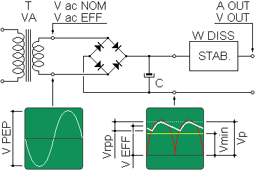
| Secondary peak-to-peak voltage relative to the applied load | V PEP | ||
| Rectifier + filter capacitors : | |||
| Rectified voltage related to the applied load | Vp | ||
| RMS Rectified voltage related to the applied load | V EFF | ||
| Output ripple related to the applied load and to the filter capacity choosed | Vrpp | ||
| Real usable voltage by the voltage regulator (stabilizer) Vp - Vrpp - Vreg. | Vu | ||
| Rectifier considered voltage drop | V | ||
| Minimal dispersed power by the rectifier (bridge) with the applied load | W (diodes) | ||
| Voltage regulator (stabilizer) : | |||
| Miminum required voltage in input by the stabilizer. For the correct functioning it must be lower than the Vu. | Vmin | ||
| Minimum power dispersed by the stabilizer with the applied load | W (reg) | ||
| Various : | |||
| Maximum global efficiency of the power supply with the applied load | % | ||
Notes.
Voltage drop on the secondary caused by the load can change in function of
construction or designing of the transformator itself.
The no-load output voltage of the transformator is obtained summing the expected drop at the maximum power at the nominal voltage. Pratically the output voltage at the nominal power will be equals to the nominal voltage.
The output ripple (Vrpp) can change in function of the quality of the used capacitors.
The ripple value (Vrpp) is made reasonably valid up to 50% of V RMS, beyond this value the inaccuracy increases.
Normally a supply must be able to work correctly with supply voltages which can change at least of +/- 10% respect to the nominal or the project value.
The voltage difference between the input and the output of the stabilizer depends on the kind of circuit and on the numer of junctions interested by the current passage. It is a value that increase with the increasing of the load, for example on a 7805 with maximum admitted current is 2 V.
The power dissipated by the regulator is what You have to consider when you design the heat sink.
To obtain the minor possible ripple on the stabilizer output is necessary that the minimum ripple voltage in input is never lower than Vmin.
The applications for powersupply.